Analog Printed Spiking Neuromorphic Circuit
June 29, 2025 | 1,205 words | 6min read
It’s been a while since I listened to the lecture on Computer Organization, which covers circuits and related topics. As a result, I’m a bit rusty, and it’s more likely than usual that I got something wrong in this paper. Please keep that in mind while reading.
Paper Title: Analog Printed Spiking Neuromorphic Circuit
Link to Paper: https://core.ac.uk/download/pdf/596774544.pdf
Date: 25. March 2024
Paper Type: Neuromorphic Computing, SNN, Printed Electronics, Circuit Design
Short Abstract:
This paper introduces a novel design for an Analog Printed Spiking Neural Network (P-SNN) using printed electronics, aimed at creating a low-power and efficient neuromorphic system.
1. Introduction
Modern devices: such as small robots, IoT devices, and wearable technology, all require power-efficient and low-cost solutions. These characteristics are often not met by traditional silicon-based circuits.
An alternative to these circuits could be neuromorphic computing. Neuromorphic computing uses Spiking Neural Networks (SNNs), which, in contrast to traditional Artificial Neural Networks (ANNs), are inspired by the biology of the brain and neurons. SNNs use spikes, making them event-driven and therefore more power-efficient, as they don’t require continuous energy consumption.
Additional research has been done on Analog Artificial Neural Networks (P-ANNs), which, as the name suggests, use analog instead of digital signals and are printed directly onto circuits.
The authors propose to combine the benefits of P-ANNs with SNNs, thereby introducing Printable Spiking Neural Networks (P-SNNs). To enable this, they design a special printable circuit suitable for implementing SNNs.
2. Background
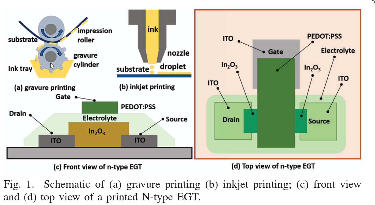
Printed Electronics (PE) is an additive manufacturing process in which layers of materials are deposited on a substrate to create circuits and, eventually, entire devices. PE offers several advantages: it is inexpensive, flexible (i.e., compatible with a variety of materials), and highly scalable.
Two common printing techniques are:
- Gravure printing
- Customized jet printing, which comes in two types:
- Organic: Requires voltages higher than 5V
- Inorganic: Can operate with voltages below 1V
Printed Artificial Neural Networks (P-ANNs) are neural networks emulated using circuits composed of resistors and transistors created through printing techniques. The resistors in these networks are implemented using a structure known as a crossbar.
3. Printed Spiking Neural Networks (P-SNN)
3.1 Implementation of a Printed Spiking Neuron
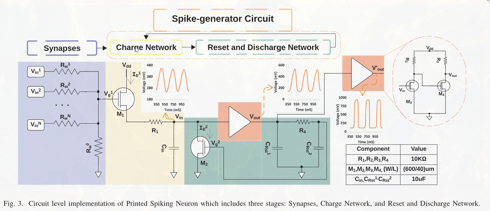
A typical P-SNN neuron consists of three main components:
- Synapses: The input connections to the neuron.
- Charge Network: Responsible for maintaining the internal membrane potential, which tracks the current state of the neuron (i.e. how much charge it holds).
- Reset and Discharge Network: Responsible for decaying the membrane voltage over time and resetting it after the neuron fires.
The synapses can be modeled with the following equation:
$$ \frac{V_g^1}{R_w^0} + \frac{V_g^1 - V_{in}^1}{R_w^1} + \cdots + \frac{V_g^1 - V_{in}^N}{R_w^N} = 0 $$Where \(V\) denotes voltage and \(R_w\) are the resistors (i.e., weights).
3.2 Understanding the Circuit
Synapses Each neuron has multiple synapses, represented by inputs \(V_{in}^1, V_{in}^2, \ldots, V_{in}^N\). These inputs are encoded as voltages — the stronger the input signal, the higher the voltage. Each synapse includes a resistor \(R_w^i\), which acts as the synaptic weight. A higher resistance allows less current to pass through, reducing the influence of that input. The synapses are connected in parallel, effectively summing the weighted inputs. The resistor \(R_w^0\) grounds the synaptic network, ensuring the voltage is defined even when no inputs are active.
Charge Network The charge network includes a control gate \(V_g^1\), which behaves like a valve. The higher the input voltage, the more it affects the flow of current from the supply voltage \(V_{dd}\) to a capacitor \(C_{in}\), which represents the neuron’s internal membrane. The capacitor stores charge, thus encoding the neuron’s current activation level. A ground connection ensures a defined state even when both the capacitor and inputs are empty.
Reset and Discharge Network Another gate, \(V_g^2\), manages the reset mechanism. When the neuron fires, this gate closes, discharging the capacitor through a transistor \(M_2\) to ground. This resets the neuron and prepares it for the next input spike. The signal from the charge network is passed through an amplifier to produce \(V_{out}\), and then further amplified to produce \(V_{out}'\), making the output usable for the next stage in the network.
3.3 Training of P-SNN
Now that we’ve defined the model and circuit and seen how it functions, we need to train the model — that is, determine the input weights of the synapses \(R_w^1, \ldots, R_w^N\).
However, training directly on the physical circuit is difficult. Backpropagation is not feasible on hardware, so instead, we use surrogate training: we digitize the circuit, train it on a GPU, and once training is complete, we print the circuit with the learned weights fixed.
How does this work? The process consists of the following steps:
1. Rebuild the circuit in simulation software
- The circuit is reconstructed in a simulation tool such as SPICE.
- A series of simulations are then run with:
- Constant voltages as input
- Fixed synaptic weights
- Each simulation produces a mapping between input voltages and corresponding output voltages.
- The resulting dataset is split into training, validation, and test sets.
Note: At this stage, we’re not training the neural network; instead, we’re generating a dataset that will be used for training a surrogate model.
2. Train a surrogate model
- A transformer-based surrogate model is trained on this dataset.
- This model simulates a single neuron from the physical circuit.
- Input: constant voltage values ranging from 0V to 2V
- Optimization: Adam optimizer
- Loss function: Mean Squared Error (MSE) between the surrogate model’s output and SPICE simulation output
The goal is to approximate the mapping:
$$ V_g(t) \longrightarrow V_{\text{out}}(t) $$
3. Use the trained neuron in a larger P-SNN architecture
- The trained surrogate neuron (SG neuron) is used as a component in a full network.
- Instead of simulating the physical circuit or running SPICE for each neuron, the network now computes: $$ \text{SG}\left( \sum V_i^{\text{in}} \cdot w_i \right) \longrightarrow V_{\text{out}}(t) $$
- Here, \(w_i\) are now trainable weights.
- The entire network is differentiable and can be trained on a GPU like a standard ANN.
4. Train the full P-SNN on target data
- The network is trained using cross-entropy loss, modified slightly to incorporate the temporal aspects of SNNs.
- This is done using the actual dataset for the intended task e.g., image classification.
5. Deploy by printing the trained network
- Once training is complete, the learned weights are fixed and the circuit is printed.
- Important: After printing, the weights are physically embedded in the circuit and cannot be updated. If the weights need to change, a new circuit must be printed.
4. Experiments
4.1 Setup
- They used Cadence Virtuoso to simulate the power behavior of the model via SPICE.
- For training and evaluation, they used 13 different benchmark datasets.
- The network was trained using the Adam optimizer with an initial learning rate of 0.1, and a scheduler that halves the learning rate when no improvement is observed.
- For comparison, they also implemented a P-ANN (Printed Artificial Neural Network) with the same architecture/topology as their proposed P-SNN.
- Power consumption of the circuits was estimated through SPICE simulations.
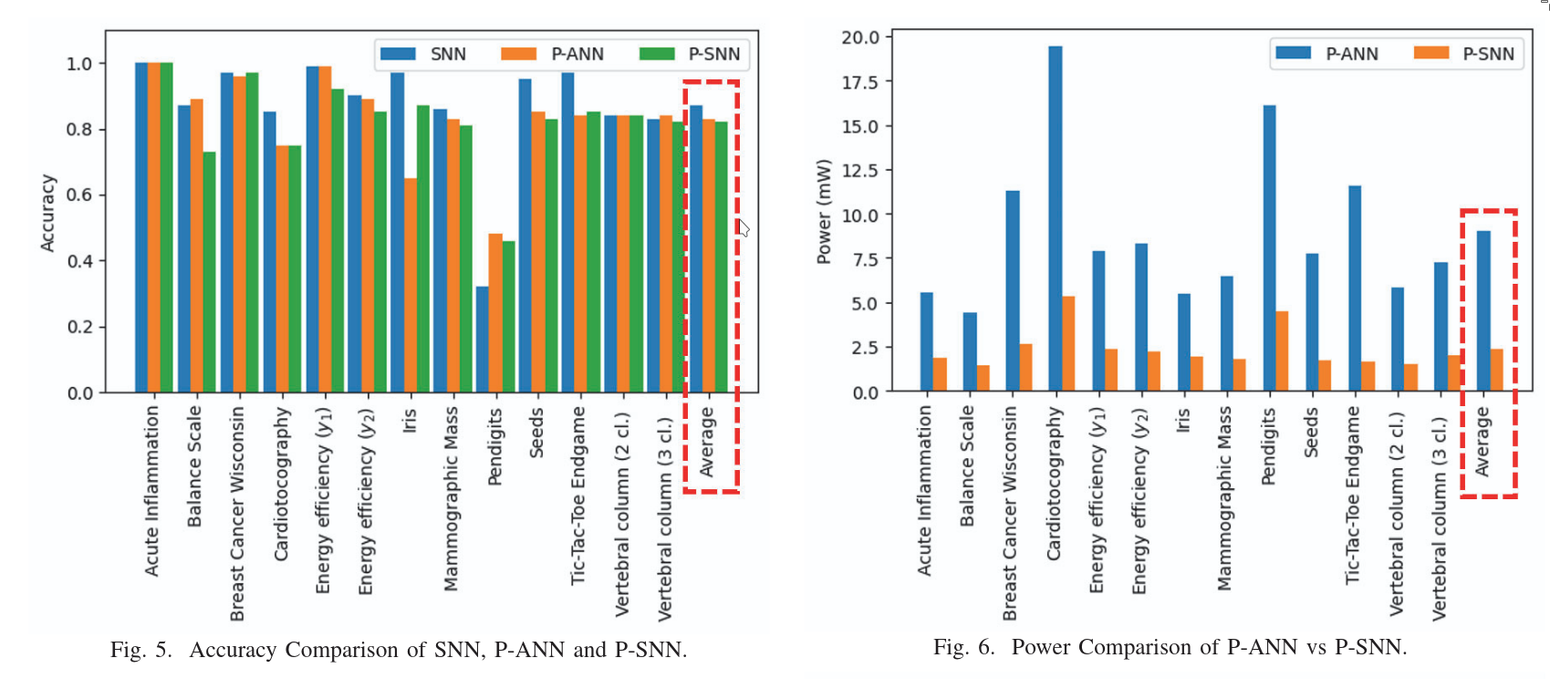
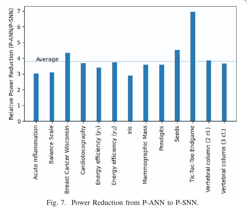
4.2 Results
5. Conclusion
This is the first Printable Spiking Neural Network (P-SNN) that combines a spiking neural network with a transformer architecture and is fully printable as a circuit. It achieves comparable accuracy to existing methods like P-ANN, while offering significantly improved power efficiency.
 reply via email